In the last article Introduction to clean architecture: Part 1, we saw how clean architecture is a set of principles for designing software such that the purpose of a software program is clear on seeing its code and the details about what tools or libraries are used to make it are buried deeper, out of sight of the person who views it. This is in line with real world products such as buildings and kitchen tools where a user knows what they are seeing rather than how they are made.
In this article, we will see how a very simple program is designed using clean architecture. I am going to present only the blueprint of a program. I won’t use any programming language, staying true to one of the principles of clean architecture, i.e. it doesn’t matter which programming language is used.
The simple program
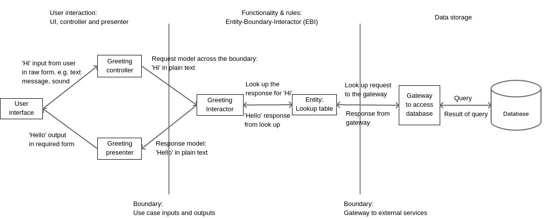
In our program, we will allow our system to receive a greeting ‘Hi’ from the user while greeting him/her back with a ‘Hello’. That’s all we need to study how to produce a good program blueprint with clean architecture.
Where do we start
I have outlined this in the post An effective 2-phase method to gather client requirements. When given a problem, we must always start with who the user are and how the system work from their points of view. Based on the users, we should build possible use cases.
In our system, we have a single user who greets our system. Let’s call him/her the greeter. Let’s just use the word ‘system’ to describe our greeting application. We have just one case in our system which we can call, ‘Greet and be greeted back’. Here’s how it will look.
- The greeter greets our system.
- On receiving the greeting ‘Hi’ (and only ‘Hi’), our system responds with ‘Hello’, which the greeter receives.
- Any greeting other than ‘Hi’ will be ignored and the system will simply not respond.
This simple use case has two aspects.
- It comprehensively covers every step in the use case covering all inputs and outputs. It distinctly says that only a greeting of ‘Hi’ will be responded to and that other greetings will be ignored without response. No error messages, etc.
- The use case also has obvious omissions. The word ‘greet’ is a vague verb which doesn’t say how it’s done. Does the greeter speak to the system and the system speak back. Does the greeter type at a keyboard or use text and instant messaging? Does the system respond on the screen, shoot back an instant message or send an email? As far as a use case is concerned, those are implementation details, the decisions for which can be deferred for much later. In fact, input and ouput systems should be plug-and-play, where one system can be swapped for another without any effect on the program’s core working, which is to be greeted and to greet back.
The EBI system
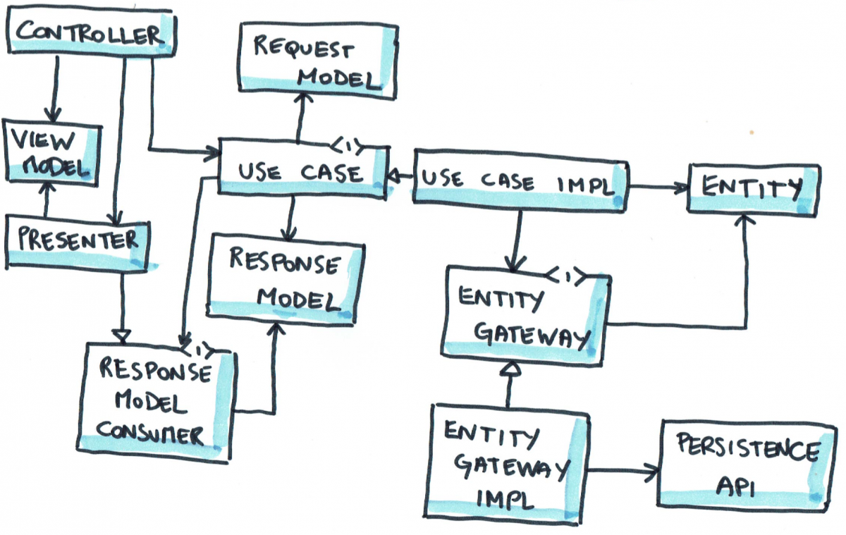
Once the requirements are clear, we start with the use cases. The use case is the core of the system we are designing and it is converted into a system of parts known as the EBI or Entity-Boundary-Interactor. There are 5 components within the EBI framework. Every use case in the system is converted to an EBI using these five parts.
Interactor (I): The interactor is the object which receives inputs from user, gets work done by entities and returns the output to the user. The interactor sets things in motion like an orchestra director to make the execution of a use case possible. There is exactly one interactor per use case in the system.
Entities (E): The entities contain the data, the validation rules and logic that turns one form of input into another. After receiving input from the user, the interactor uses different entities in the system to achieve the output that is to be sent to the user. Remember that the interactor itself must NEVER directly contain the logic that transforms input into output. In our use case, our interactor uses the services of an entity called GreetingLookup. This entity contains a table of which greeting from the user should be responded to with which greeting. Our lookup table only contains one entry right now, i.e. a greeting of ‘Hi’ should be responded to with ‘Hello’.
Usually, in a system that has been meant to make things easy, automated or online based on a real world system, entities closely resemble the name, properties and functionality of their real world equivalents. E.g. in an accounting system, you’ll have entities like account, balance sheet, ledger, debit and credit. In a shopping system, you’ll have shopping cart, wallet, payment, items and catalogues of items.
Boundaries (B): Many of the specifications in a use case are vague. The use case assumes that it receives input in a certain format regardless of the method of input. Similarly it sends out output in a predetermined format assuming that the system responsible for showing it to the user will format it properly. Sometimes, an interactor or some of the entities will need to use external services to get some things done. The access to such services are in the form of a boundary known as a gateway.
E.g., in our use case, our inputs and outputs may come from several forms such as typed or spoken inputs. The lookup table may seek the services of a database. Databases are an implementation detail that lie outside the scope of the use case and EBI. Why? Because, we may even use something simpler such as an Excel sheet or a CSV file to create a lookup table. Using a database is an implementation choice rather than a necessity.
Request and response model: While not abbreviated in EBI, request and response models are important parts of the system. A request model specifies the form of data that should be sent across the boundaries when requests and responses are sent. In our case, the greeting from the user to the system and vice-versa should be sent in the form of plain English text. This means that if our system works on voice-based inputs and outputs, the voices must be converted to plain English text and back.
Controllers
With our EBI system complete to take care of the use case, we must realise that ultimately the system will be used by humans and that different people have different preferences for communication. One person may want to speak to the system, while another prefers instant messaging. One person may want to receive the response as an email message, while another may prefer the system to display it on a big flat LCD with decoration.
A controller is an object which takes the input in the form the user gives and converts it into the form required by the request model. If a user speaks to the system, then the controller’s job is to convert the voice to plain English text before passing it on to the interactor.
Presenters
On the other side is a presenter that receives plain text from the interactor and converts it into a form that can be used by the UI of the system, e.g. a large banner with formatting, a spoken voice output, etc.
Testability
Being able to test individual components is a big strength of the clean architecture system. Here are the ways in which the system can be tested.
Use case: Since the use case in the form of EBI is seperated from the user interface, we can test the use case without having to input data manually through keyboards. Testing can be automated by using a tool that can inject data in the form of the request model, i.e. plain text. Likewise the response from the use case can be easily tested since it is plain text. Also individual entities and the interactor can be seperately tested.
Gateway: The gateways such as databases or API calls can be individually tested without having to go through the entire UI and use case. One can tools that use mock data to see if the inputs to and outputs from databases and services on the Internet work correctly.
Controllers and presenters: Without involving the UI and the use case, one can test if controllers are able to convert input data to request model correctly or if presenters are able to convert response model to output data.
Freedom to swap and change components
Interactors: Changes to the interactors are often received well by the entire system. Interactors are usually algorithms and pieces of code that bind the other components together, usually a sequence of steps on what to do. Changes to the steps does not change any functionality in the other components of the system.
Entities: Entities are components that contain a lot of data and rules relevant to the system. Changes to entities will usually lead to corresponding changes in the interactor to comply with the new rules.
Boundaries: Boundaries are agreements between the interactor and external components like controllers, presenters and gateways. A change to the boundary will inevitably change some code in the external components, so that the boundary can be complied.
UI: With a solid use case in place, you can experiment with various forms of UI to see which one is most popular with your users. You can experiment with text, email, chat, voice, banner, etc. The use case and the gateway do not change. However, some changes to the UI can cause a part of the controller and the presenter to change, since these two are directly related to how the UI works.
Controller and presenter: It is rare for the controller or presenter to change in their own rights. A change to the controller or presenter usually means that the UI or the boundary has also changed.
Conclusion
Clean architecture seperates systems such that the functionality is at the core of the system, while everything like user interface, storage and web can be kept at the periphery, where one component can be swapped for another. Hopefully, our example has given you a good idea about how to approach any system with clean architecture in mind.