Information technology is a means to automate your day-to-day tasks. But before we build systems, we need to know why we are building them. There is no way to know this unless we first gather a system’s requirements. We need to talk to various people who have a stake in the soon to be built system.
The meetings are often voice conversations and it becomes really important to record what was spoken so that there is a permanent reference. In this article, I explain a two-phase documentation system to thoroughly record a system’s requirements using UML diagrams — storyboarding and timelines.
Note that UMLs were started in information technology and software engineering. But they can be used to document the requirements for any kind of solution building.
1. Storyboarding: Users and their use cases
Users
The first component of a system that needs to be identified is who will use it. There may be multiple types of users for a system. They are also called stake-holders. Users may be human users or other systems.
Every user has a point of view into the system. That point of view shows what that user wants to achieve by using the system. The user identification step can be built upon incrementally rather than in a single sitting. If you see that more types of users can benefit from the system later, they and their use cases can be added later.
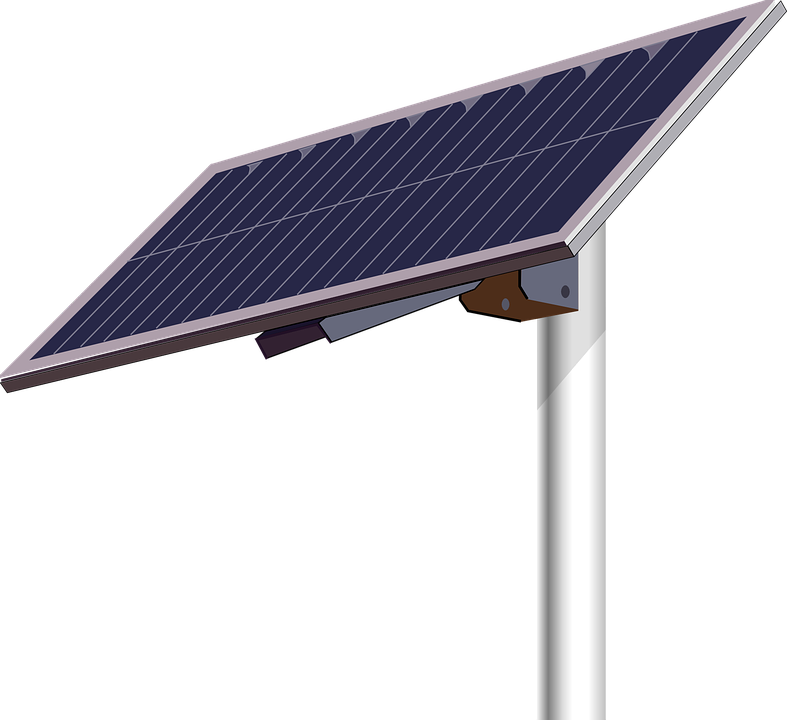
An example: Let us consider the example of a solar panel charger system. The following users can be said to interact with the system.
- Consumer
- Service personnel
Use cases
Users use a system in different ways. Each type of usage leads to a narrative. Each narrative is called a use case. While drawing a use case diagram, an exhaustive list of all types of ways that a user can use the system for, is prepared and represented in a diagram.
Considering our solar charger system example, let us consider the consumer. The consumer will have the following types of usage.
- Charge the system: Expose the solar panel to sunlight for charging.
- Use residual charge in the system: Connect an electronic device to the panel for usage.
2. Narrative: Sequence
After all the users’ use cases have been identified, it is time to document each use case exhaustively. The flow of each use case is documented in as much detail as possible. Along with the normal and successful flows, failed flows are also included. Every detail about inputs and outputs that the flow generates are recorded.
Let us look at the ‘Charge the solar panel’ use case as an example of how to make a use case flow.
- The consumer places the solar panel of the system such that it is exposed to sunlight.
- The solar panel attempts to draw the incident sunlight and convert it into a potential difference (voltage).
- The potential difference activates a controller circuit in the panel. If there is sufficient potential difference, current starts flowing through the controller circuit.
- If sufficient current flows through the controller, it activates a yellow LED on a panel of LEDs to show the user that the system has started charging with sufficient power.
- Failure 1: If there is not enough sunlight available, the potential difference and the current will be low. In that case, a low powered blinking red light is shown to the consumer.
- The potential difference is applied to a connected battery, which starts charging.
- Once the battery reaches 100% charge, the controller turns off the yellow light and shows a green light.
- The consumer may move the panel away from sunlight.
The steps have been outlined in good detail. The failure case, where there is not enough sunlight, has been taken care of. Let us now see the sequence diagram for the above description.
Conclusion
The two-phase system described in this post is absolutely vital before we can proceed to design a system. This will avoid false starts and assumptions about what the users of a system need. Instead, requirements are gathered systematically in paper form (or digital document form), before the first line of code is written or the first hole drilled of the first wire is soldered into an electronic circuit.
Further reading
- 4 elementary must-have skills for a software engineer, one of which is drawing UML diagrams.


2 thoughts on “Using UML diagrams: A 2-phase method to gather software requirements”